GPIO 6 is used as a USB power switch
GPIO 8 is connect to the toggle switch
reset is on?
Then there is the 6 pin header and the header with the LEDS
How are those wired up?
GPIO 6 is used as a USB power switch
GPIO 8 is connect to the toggle switch
reset is on?
Then there is the 6 pin header and the header with the LEDS
How are those wired up?
@Frietpan: Does this image make some things clear to you?

Can be found on the specifications page: 404 Page not found - GL.iNet
If you drill out a little part of the enclosure the switch also uses GPIO 7 when switch the switch to the right. See my post in an other topic how to make use of it: 404 Page not found - GL.iNet
Thanks!
I see I’m already running behind thats a very nice writeup Jeroen, great stuff!
Is there also info available about the PoE header. Is there also any GPIO used or is that all wired to the RJ45?
I don’t know any information about the PoE module. I also would like to see / know more about it. Just wondering how it looks like and how it works.
Yea so do I. I mainly wonder how this stuff is grounded. At first i thought it where the same GPIO’s as in the 6416A but now I see it is far different from that.
PoE is connected to RJ45. But there are two pins one the far right in the picture is GND and 5V.
So the 5 pins left do recieve the power through the UTP-cable / RJ56 sockets and the most right 2 pins do power 5V to the PCB of the GL-AR150?
Yes.
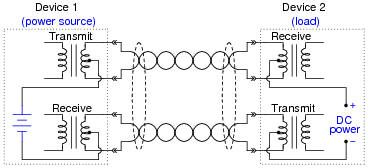
So the DC current is ‘injected’ cable and the PHY chips then decouple the data signal (AC).
The PHY’s galvanic decoupling transformer Blocks the DC component. And the AC component is transformed over to the SoC.