Hi There,
I just received my AR150 with the SD3077 RTC module. I followed the documentation here: RTC Setting - GL.iNet Docs
But when I give the hwclock -r command, it gives me an error:
root@OpenWrt:~# hwclock -r
hwclock: RTC_RD_TIME: No such device or address
root@OpenWrt:~# hwclock -r
hwclock: ioctl(RTC_RD_TIME) to /dev/rtc0 to read the time failed: No such device or address
root@OpenWrt:~# hwclock --verbose
hwclock from util-linux 2.32
System Time: 1615499032.780573
Trying to open: /dev/rtc0
Using the rtc interface to the clock.
Assuming hardware clock is kept in UTC time.
Waiting for clock tick…
ioctl(3, RTC_UIE_ON, 0): Invalid argument
Waiting in loop for time from /dev/rtc0 to change
hwclock: ioctl(RTC_RD_TIME) to /dev/rtc0 to read the time failed: No such device or address
…synchronization failed
Use GL.iNet download center firmware does not necessarily can, could you please confirm whether the previous steps are successful?
Can you give me all the execution steps
I tried with the stock firmware and the clean one too. Non of them works. Here are the steps:
opkg update
opkg install kmod-i2c-gpio-custom
opkg install kmod-rtc-sd2068
insmod i2c-gpio-custom.ko bus0=0,1,17
echo sd2068 0x32 > /sys/bus/i2c/devices/i2c-0/new_device
root@OpenWrt:~# hwclock -r
hwclock: ioctl(RTC_RD_TIME) to /dev/rtc0 to read the time failed: No such device or address
Hi Gabor, There isn’t the product(AR150+RTC) in my office, I need to pick up the product from our factory. It will take some time, please wait one or two days.
Hi Hoff,
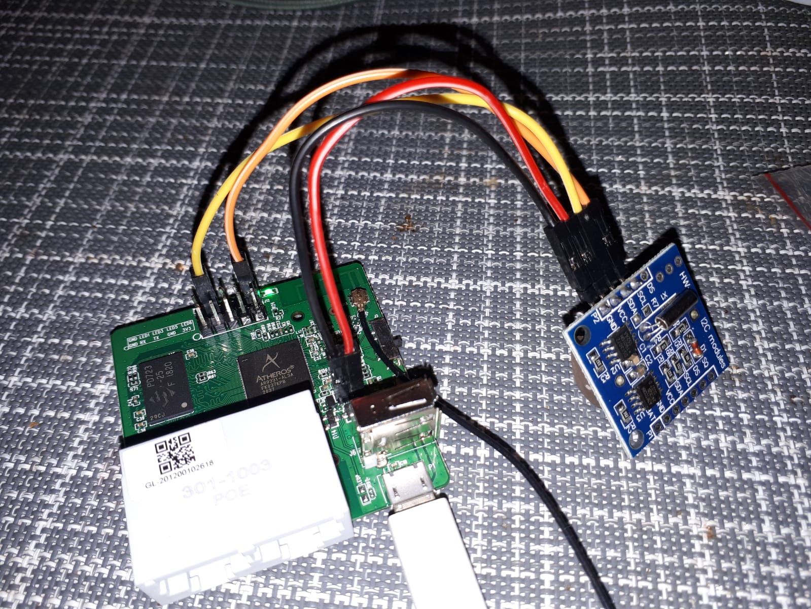
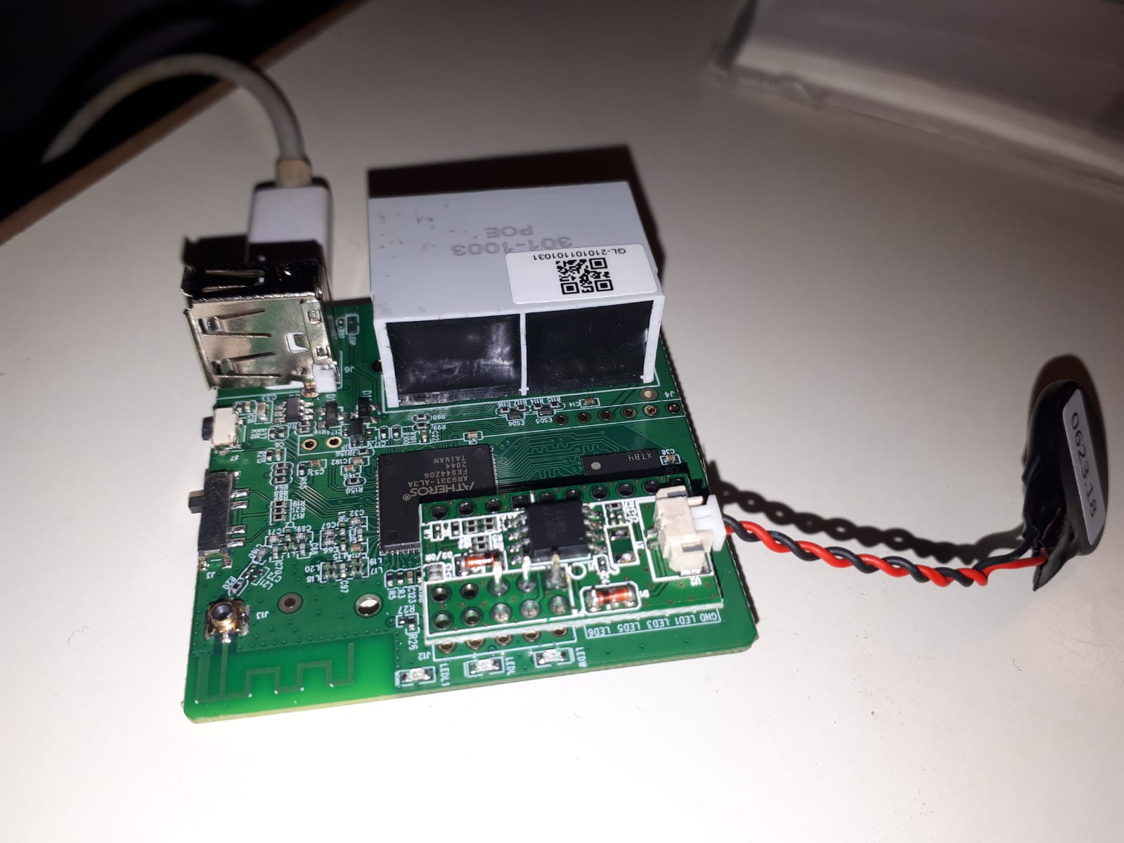
ouch, this is very unfortunate. I tried to unsolder the module to add more pins to the AR150 board - because they aren’t enough in mine, only that 3 pins. When I unsoldered it, the tiny rings (where the pins was soldered) came off from the RTC module, so I can’t solder it back. I guess I broke it, and I don’t have any other. And I didn’t find any in Europe webshops. I suggest to change that photo in your howto documentation, this could be very misleading for your future buyers since there are only 3 pins soldered in the AR150 board anyways. I still have some DS1307 module (Tiny RTC - Elecrow), will try to install this.
Thanks for your support,
Regards,
Gabor
Hi Alzhao! Why to check in the Domino Core’s docs?
In AR150’s documentation the command to install the module is: insmod i2c-gpio-custom.ko bus0=0,1,17
That’s why I guess it’s I2C. It isn’t???
Hi gabor, there isn’t real I2C in this board, we use emulate i2c.
In this command insmod i2c-gpio-custom.ko bus0=0,1,17, it’s means: gpio1 is configured as SDA, and gpio17 is configured as SCL.
You can change other pins to connect you Tiny RTC on this board, and if you change, you must change the gpio in this command insmod i2c-gpio-custom bus0=0,SDA,SCL.
For examply, if you use GPIOx to connect Tiny RTC’s SDA, use GPIOy to connect Tiny RTC’s SCL, you should configure GPIOx as SDA and configure GPIOy as SCL,the command like this: insmod i2c-gpio-custom bus0=0,GPIOx,GPIOy

