Cool! Thanks!
BE6500 VLAN and WIFI Configuration via SSH/UCI and LuCI
Previously in Reference 2, a sample of Lan based iot Vlan on BE6500 was created via SSH/UCI scripting and via LuCI GUI, without using network Bridge device. However, a Vlan bridge device is necessary for adding/binding a wifi ssid to a specific Vlan.
References
Ref.1 @bruce @will.qiu : https://forum.gl-inet.com/t/flint-3-gl-be9300-as-ap-behind-pfsense-multiple-ssids-vlan-random-bssid/66719
Ref.2
This is a follow-up descripting BE6500 wifi creation for specific Vlan, an IOT (Vlan 21) in this example, via SSH/UCI scripting and via LuCI GUI.
Environment:
· Same as those listed in Ref.2
· Plus: Create 2.4Ghz and 5Ghz wifi and bind their SSIDs to IOT (Vlan 21) network, so that wireless devices are in the same Vlan network.
Pre-condition:
· BE6500 is manufactured reset
· Basic Wan/Lan settings completed
Two approaches:
- VLAN & VLAN Based Wifi Configuration via SSH/UCI script
- VLAN & VLAN Based Wifi Configuration via LuCI GUI
Part 1 - BE6500 VLAN & Wifi Configuration via SSH/UCI script
Compared with Lan based Vlan configuration described in Ref.2, following additional steps are added:
· Bridge device (for iot) to allow binding Wifi ssid to iot Vlan
· 2.4 GHz wifi binding with iot Vlan
· 5Ghz wifi binding with iot Vlan
Wifi related UCI script was largely derived from @bruce code in Ref.1, with minor modifications.
Use SSH or PuTTY (login as root) and run following UCI script
#Create VLAN 21 (IOT)
#Setup Physical Lan Port 1 as trunk port for downstream AP/switch
#swconfig Switch 1 Port 3 = cpu
#swconfig Switch 1 Port 7 = Physical Lan Port 1

uci set network.vlan_iot='switch_vlan'
uci set network.vlan_iot.device='switch1'
uci set network.vlan_iot.vlan='21'
uci set network.vlan_iot.ports='3t 7t'

#Create sub-interface/device for VLAN 21

uci set network.eth1_21='device'
uci set network.eth1_21.name='eth1.21'
uci set network.eth1_21.type='8021q'
uci set network.eth1_21.ifname='eth1'
uci set network.eth1_21.vid='21'

# Add Bridge
uci set network.br_iot=device
uci set network.br_iot.type='bridge'
uci set network.br_iot.name='br-iot'
uci add_list network.br_iot.ports='eth1.21'


#Create the IOT interface

uci set network.iot='interface'
uci set network.iot.device='br-iot'
uci set network.iot.proto='static'
uci set network.iot.ipaddr='192.168.21.1'
uci set network.iot.netmask='255.255.255.0'

#Enable DHCP for IOT

uci set dhcp.iot='dhcp'
uci set dhcp.iot.interface='iot'
uci set dhcp.iot.start='100'
uci set dhcp.iot.limit='150'
uci set dhcp.iot.leasetime='12h'


#Create the IOT firewall zone

uci add firewall zone
uci set firewall.@zone[-1].name='iot'
uci set firewall.@zone[-1].network='iot'
uci set firewall.@zone[-1].input='REJECT'
uci set firewall.@zone[-1].output='ACCEPT'
uci set firewall.@zone[-1].forward='REJECT'
uci set firewall.@zone[-1].masq='1'
uci set firewall.@zone[-1].mtu_fix='1'

#Allow IOT to access WAN

uci add firewall forwarding
uci set firewall.@forwarding[-1].src='iot'
uci set firewall.@forwarding[-1].dest='wan'

#Allow DHCP & DNS on IOT

uci add firewall rule
uci set firewall.@rule[-1].name='Allow-IOT-DHCP'
uci set firewall.@rule[-1].src='iot'
uci set firewall.@rule[-1].proto='udp'
uci set firewall.@rule[-1].dest_port='67-68'
uci set firewall.@rule[-1].target='ACCEPT'

uci add firewall rule
uci set firewall.@rule[-1].name='Allow-IOT-DNS'
uci set firewall.@rule[-1].src='iot'
uci set firewall.@rule[-1].proto='tcp udp'
uci set firewall.@rule[-1].dest_port='53'
uci set firewall.@rule[-1].target='ACCEPT'


#Add WiFi SSID Radio - 5G

uci set wireless.wifi5g1=wifi-iface
uci set wireless.wifi5g1.device='wifi1'
uci set wireless.wifi5g1.network='iot'
uci set wireless.wifi5g1.mode='ap'
uci set wireless.wifi5g1.ssid='GL Router-iot-5G'
uci set wireless.wifi5g1.encryption='psk2+ccmp'
uci set wireless.wifi5g1.key='goodlife'
uci set wireless.wifi2g2.wds='1'
uci set wireless.wifi5g1.isolate='0'
uci set wireless.wifi5g1.hidden='0'
uci set wireless.wifi5g1.ieee80211k='1'
uci set wireless.wifi5g1.bss_transition='1'
uci set wireless.wifi5g1.sae='0'
uci set wireless.wifi5g1.disabled='0'

#Add WiFi SSID Radio - 2.4G

uci set wireless.wifi2g1=wifi-iface
uci set wireless.wifi2g1.device='wifi0'
uci set wireless.wifi2g1.network='iot'
uci set wireless.wifi2g1.mode='ap'
uci set wireless.wifi2g1.ssid='GL Router-iot-2.4G'
uci set wireless.wifi2g1.encryption='psk2+ccmp'
uci set wireless.wifi2g1.key='goodlife'
uci set wireless.wifi2g2.wds='1'
uci set wireless.wifi2g1.isolate='0'
uci set wireless.wifi2g1.hidden='0'
uci set wireless.wifi2g1.ieee80211k='1'
uci set wireless.wifi2g1.bss_transition='1'
uci set wireless.wifi2g1.sae='0'
uci set wireless.wifi2g1.disabled='0'


#Commit and Reboot

uci commit
reboot
Newly added 2.4Ghz/5Ghz Wifi are activated and configurations are present in both
· GL-BE6500 Admin Panel / WIRELESS, and
· LuCY->Network->Wireless
Part 2: BE6500 VLAN & Wifi Configuration via LuCI GUI
2.1 Setup VLAN 21 network
As mentioned in Ref.2, VLAN 21 network setup via LuCI GUI has following 6 steps:
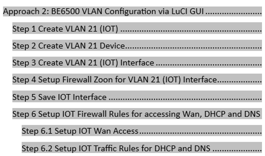
Network bridge device was optional (not necessary) for Lan based Vlan, and the network bridge was not created from the above steps. However, to add/bind wifi into a Vlan network, a network bridge device is required.
To add a Vlan based Bridge device, Step 3 listed above needs to be revised as follow:
Step 3 Create VLAN 21 (IOT) Bridge and Interface
Step 3.1 Create IOT Bridge Device: br-iot
· LuCI->Network->Interfaces->devices
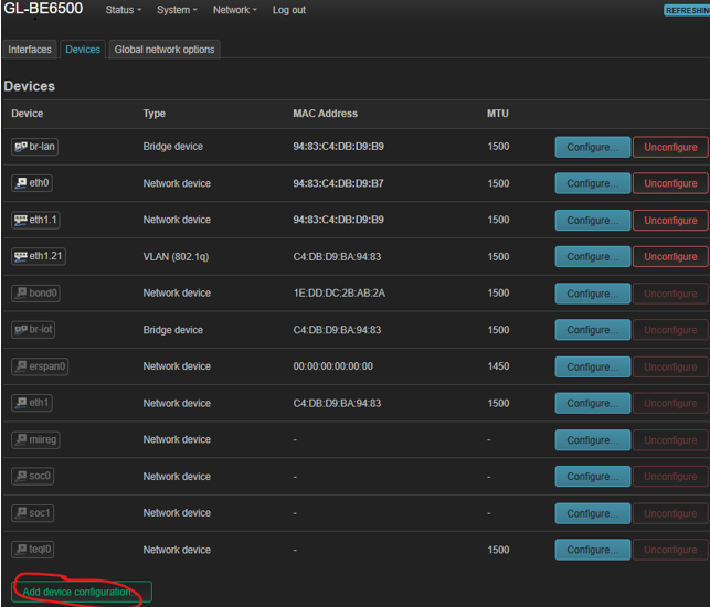
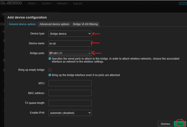
· Click “Add device Configuration”, and select/input info as below, then click Save
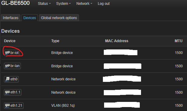
Now Vlan21 bridge device “br-iot” is created
Step 3.2 Create VLAN 21 (IOT) Interface
· LuCI->Network->Interfaces->Interfaces
· Go to bottom of the page and Click “Add new interface”
     Name: iot
     Protocol: Static address
     Device: select “br-iot”
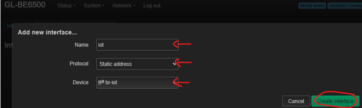
· Click “Create interface”
· Add IPv4 address/netmask: 192.168.21.1/255.255.255.
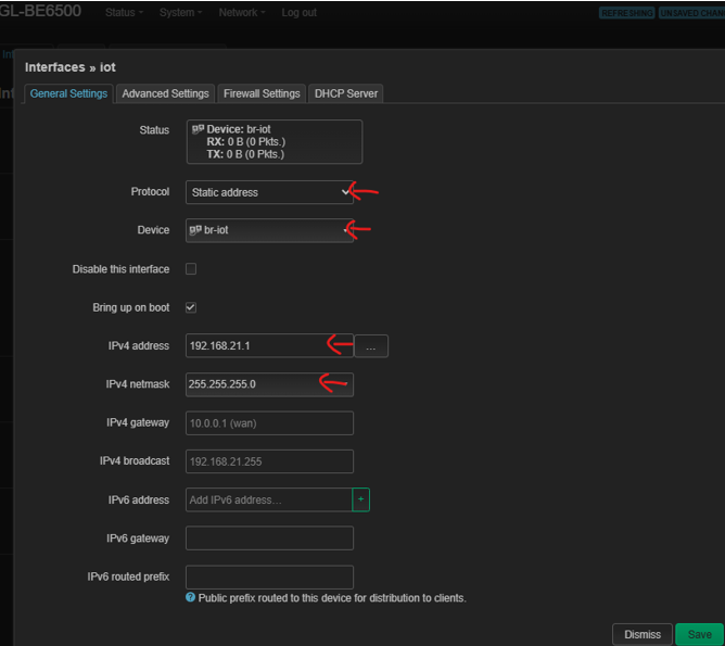
Do not Save.
This is the end of revised Step 3, Continue rest of steps to complete the Vlan 21 network configuration.
2.2 Setup 2.4Ghz/5Ghz wifi for VLAN 21
Steps for adding both 2.4Ghz wifi and 5Ghz wifi into Vlan 21 network are identical.
Step 2.1 Choose a new 2.4Ghz or 5Ghz wifi to create
· LuCI->Network->Wireless
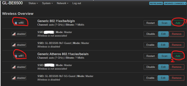
To create a 2.4Ghz wifi, go to “wifi0” line and click Add
To create a 5Ghz wifi, go to “wifi1” line and click Add
Step 2.2 Create 2.4Ghz Wifi
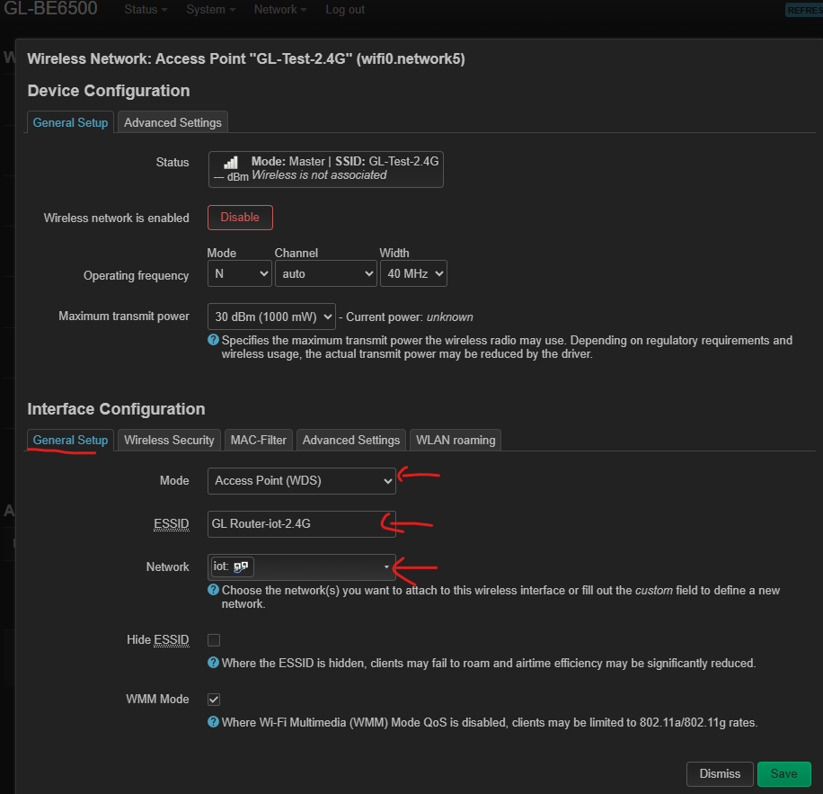
· Select from dropdown. Enter a proper SSID name in ESSID field
· Do not save
· Go to “Wireless Security” tab

· Select Encryption and Cipher from dropdown
· Enter a wifi password in Key field.
· Click “Save”
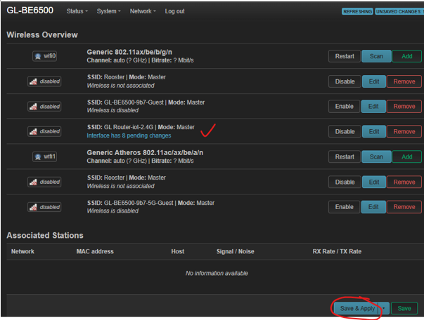
· Click Save & Apply for 2.4Ghz wifi configuration.
Step 2.3 Create 5Ghz Wifi
Repeat the same step as Step 2.2 for 5Ghz Wifi creation - consider using a different 5G ssid name
Step 2.4 Reboot Router
· LuCI->System->Reboot
Now 2.4Ghz and 5Ghz wifi SSIDs are activated. Wireless devices connected to them are sharing the same Vlan 21 network. Specific Wifi configurations are present in both
· GL-BE6500 Admin Panel / WIRELESS, and
· LuCY->Network->Wireless
1 Like
Hello, forum. I got the router back. Time to start playing with it again.
To my surprise GL.Inet has not been able to get a decent firmware on this device.
I am not here to complaint, but in all honesty this firmware feels rush to market.
I keep getting this error due to a switch Zero that has nothing attach to it!!!
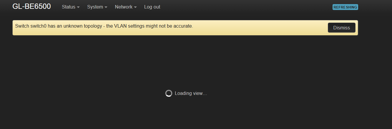
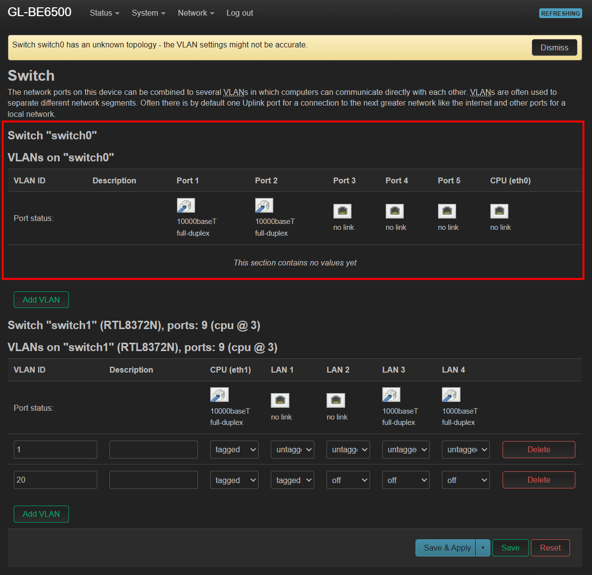
This is the default configuration.
Hello,
The appearance of switch0 in LuCI is a misidentification by the interface. Please note that this represents the internal packet processing/switching engine within the SoC, rather than a discrete external switch controller.
As we are not responsible for the maintenance of LuCI, please disregard the switch0.