Beryl MT1300 has 3 Ethernet ports labeled WAN (1), and LAN (2). However, I see only one “eth0” device (CPU0) with VLAN devices defined on it and mapped to the external physical connectors and a “bridge” for the LAN ports.
Would appreciate if someone could point me to a doc or explain how physical network device is mapped out to virtual device(s).
When using 3.x firmware(openwrt 19.07 based).
Switch view:
The switch is divided into two VLANs: vlan1(port 0 1 2 3) and vlan2(port 4). vlan2 only uses two ports physically. port 6 is called CPU port which allows both vlan1 and vlan2 tagged traffic.
CPU view:
eth0 is divided into two VLAN eth0.1 and eth0.2 that are mapped to switch two VLANs.
Following command can be used to check their relation:
brctl show
swconfig dev mt7530 show
And more directly, you can check the /etc/config/network config file.
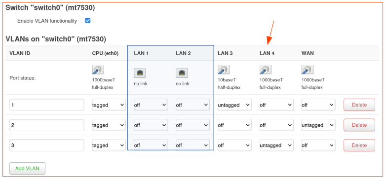
Thanks for the pointer. It helped me configure one of the “LAN” ports to a second ISP (LAN4) in the above screenshot and do load balance using mwan3.
A couple of follow up questions:
Is there a way to rename “LAN 4” to “WAN 2” and
Is there a way to remove ports LAN 1 and LAN 2 from the image displayed? The MT1300 only has three RJ45 ports. It would be great to see only the following “CPU (eth0),” “LAN 3”, “WAN 2”, and “WAN”