Hi,
is it possible to get information how are connected internal ethernets in GL-B1300?
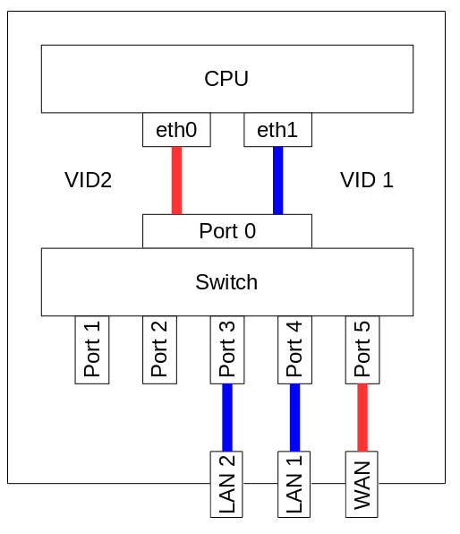
Something like (this is just an example - this is different router):
I am asking because at this moment I am really confused how it is really connected.
I found that port on internal switch are used this way:
port:0 = SoC ethernet (no idea which one exactly)
port:1 = unused (not connected)
port:2 = unused (not connected)
port:3 = LAN1
port:4 = LAN2
port:5 = WAN
But usage of SoCs eth0 and eth1 is quite foggy. It seems that eth0 is on switch port0 as untagged and eth1 is on the same(!?!) port tagged as VLAN ID 2.
So small sketch and some explanation would be very helpful.
At this moment when I for example had to set “Internet connection” and “vlan id 200 special connection” on WAN port at the same time, I had to set switch vlans as tagged port0 and untagged port5 both under vid:2 (internet connection) where SoC uses eth1 and tagged port0 and tagged port5 both under vid:200 (vlan id 200 at the wan port) but SoC has to use eth1.200 (instead of eth0.200 offered by switch) which is quite odd.
So any hint how it is connected in real would really help. Thank you.
GL-B1300 use external switch chip QCA8075.
IPQ4018 connect with QCA8075 by SGMII physically.
port 0 is cpu port which connect the whole switch.
port 1-5 is the port related to the actual physical port.
port 5 is wan while port 1-4 is lan, they are seperated
by port-based vlan.
Here you can check gmac0/eth0 has vid 2 and port map 0x20, which only indicate the port 5.
while gmac1/eth1 has vid 1 and port map 0x1e.
So SoC does have only one ethernet and eth1 is fake ethernet (simulated by eth0 with predefined/default vlan id) or has it two independent ethernets? Sorry, I am not familiar with dtsi.
I don’t want to argue with you, but… when two ethernets sharing only one switchport and where settings of one of them affects the other one… it doesn’t look like independent ethernets :-/.
By other words: I am unable to clearly define on switch that eth0 is in native vlan id 2 and eth1 in native vlan id 1 plus tagged vlan id 200 because on switch both ethernets are in the same switchport (port 0). Hence the question about how are really connected eth0 and eth1 to the internal switch.
Anyway, what should be “officially” correct solution for scenario stated in the first post, i.e. on WAN port is required to have two independent connections at the same time - one as untagged, the second one as tagged as vlan id 200?
For the tagged connection I had to use second ethernet (although it is still wan connection), because the “officially wan ethernet” doesn’t accept it (actually it accept, but no packets incoming).
(I have to recheck with Gl.iNet “clean” firmware because it seems that OpenWRT/LEDE has switched ethernets - eth0 in native vlan id 1 which is in same vlangroup with switchports 3 and 4 and eth1 in native vlan id 2 which is in same vlangroup with switchport 5)
kmarty, did you ever find or come up with a diagram similar to the one in your original post? The B1300 is starting to drive me insane…
First things first: I am using the official GL.iNet 2.272 firmware.
Question: How exactly do WAN, LAN1 and LAN2 map to eth0, eth1 and switch0? How do they map to the ports 0 to 6? What are VLAN 1 und 2 used for?
My expectation was that eth0 would map to WAN and eth1 would map to the switch, with LAN1 and LAN2 as physical interfaces. But as far as I can see the device does not operate this way.
this question could be related:
my WAN port is connected to my ISP’s fiber ONT which requires 802.1x authentication. I tried running wpa_supplicant on eth1 and it did not work, even though the the corresponding command worked on other openwrt routers.
Also, does the single pipe between switch and SoC mean that there is interference between the traffic between the switch and SOC’s eth0 and the switch’s eth1 port? for example, data going from the LAN to WAN and data going from WAN to LAN have contention at the egress of the switch’s port0. Thus, simultaneous download and upload would be capped at a total of 1gbps instead of 1gbps in either direction?