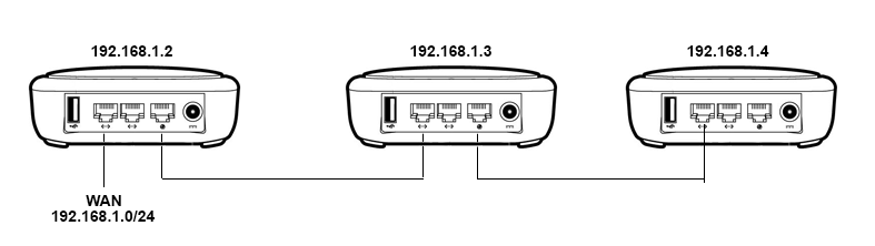
I Need to configure two physical ports as wan switch (say both ends as WAN and middle port as LAN) so I can can connect multiple B1300s as acces point, one behind another one
Something similar to this.
Are eth0 the packets from the wan port tagged as VLAN 2 and eth1 the packets from VLAN 1 from both lan ports?
How can i split the ports? for example, move the middle port from vlan 1 to new vlan 3 and then use it as eth1.3? is eth0.3 valid?
Is there a reason why you don’t just put them all on the same LAN subnet?
As they are all on the same subnet, just daisy-chain the LAN ports, turning off DHCP and DNS on the second and third unit. If you wanted to be able to easily “roam” from router to router, you could set up the same SSID on all of them.
Edit: The IPQ4018/9 SoCs have a “unique” switch architecture, at least under “upstream” (Linux/OpenWrt) support. This may be different with QSDK-based firmware. Staying away from VLAN 1 and VLAN 2 for “complex” configuration (such as VLAN trunking) is suggested. Strange results may occur if a bridge spans the WAN and LAN ports, especially if the VLAN tagging is different. To be clear, I have not tried VLAN configuration on a QSDK-based device, only on OpenWrt-based firmware.
DHCP server is in “the wan”, so it is disabled on all units, (in fact, not compiled).
I want the clients connected to that routers (middle port or wifi) in another subnet on WAN. Currently i’m doing that with a new tagged vlan on ports 5 and 3.
In another tests, I have concluded that joining the WAN and LAN ports on the switch produces strange effects, as you say.
Currently, from a computer in the wan (for example on a switch on the left port of the left router) I can connect to earch router, but if connected on the right port of the third router, i cannot access to any of them. I really don’t understand what the hell they have done with the switch
At least under OpenWrt (QSDK behavior unknown), the switch has two virtual interfaces. All packets to/from the LAN ports go to one, tagged VLAN 1 (as I recall) if untagged. Similarly, all packets to/from the WAN port go to the other, similarly tagged VLAN 2 if untagged. This is at the driver/DTS level and can’t be modified without code changes.
I personally use the WAN port on my IPQ4019-based devices as the VLAN trunk and the LAN ports as untagged access ports, explicitly specifying a different VLAN from 1 & 2.
If I try to bridge the two interfaces with a Linux bridge and, for example have VLAN 100 as tagged on the WAN port and untagged on the LAN port, connectivity fails in many cases. I haven’t chased it down any further, but I think it’s related to one interface responding to ARP requests, but the other interface (with a different MAC) being the one physically connected to the requesting device.
Here’s config I’m using on a different, IPQ4019-based device. On that device the WAN port is switch port 5 and the CPU is on switch port 0.
The DSA discussed in the below-linked thread does not yet support VLANs for the IPQ40xx devices, and is still a dead end.
I haven’t dug into this in a while, being busy shepherding the ath79 SPI-NAND support and GL-AR300M and GL-AR750S with NAND support through to OpenWrt master (finally). As my three, IPQ4019-based devices work “well enough” for me, even without having resolved the bridging of a VLAN from the trunk to the LAN ports, it hasn’t been a top priority. (Not to mention I have now have both a GL-MV1000 “Brume” and a GL-MT300N-V2 on my desk).
You can do it easily, you just need to be careful with the VLAN config.
All Qualcomm IPQ40XX SoCs with current Linux support that I am aware of. It’s an architectural “feature” of the device.
Edit:
I started to sketch something out, but I’m still at a loss as to how you want subnet things. If you want a different subnet for each device’s clients, then you’ll need three DHCP servers running, one for each subnet (or some very fancy config of a single one, probably using DHCP relays).
I’m also not sure what you mean by “WAN” in your description. Typically it refers to an interface with a public IP and, if IPv4 is in use, NAT in play. Further, if it is a separate subnet, DHCP broadcast packets aren’t routed, they are link-local only. I haven’t been able to understand what you mean by “in another subnet on WAN” either, as WAN generally refers to a single subnet.
The network where I need to install this has a server with different subnets.
By “WAN” I refer to the network where the routers get connectivity, not internet, not public IP on internet, also is the network where clients connected to that routers need to access.
I want to join two ports in the internal switch so the routers are transparent for the others, like if all GL-B1300 were connected to a switch.
There is a subnet for the access points, (WAN in my example, 192.168.1.0/24) and another subnet for the clients connected to this access points. (Let’s call it LAN, 192.168.2.0/24 for example). Routers subnet are the packets without VLAN tag,
config interface 'wan'
    option ifname 'eth1'
    option proto 'dhcp'
and clients subnet are the packets with VLAN tag 10 in my example
config interface 'wan10'
    option ifname 'eth1.10'
    option proto 'none'

config interface 'clientsbridge'
    option network 'lan wan10'
    option proto 'relay'
So the middle port is in LAN (eth0.4), wifi aps are in LAN, and packets from LAN goes “outside” with VLAN 10.
OK, so each of the routers need to connect to 192.168.1.0/24 for upstream connectivity and, it seems, for management.
Do you need a separate management VLAN?
Assuming that the desired subnets for each of the three routers are 192.168.2.0/24, 192.168.3.0/24, and 192.168.3.0/24:
Does the upstream router have static routes for 192.168.2-4.0/24? If so, how are each routed?
Does the upstream router have 192.168.2-4.0/24 on a separate VLANs?
Where are the (three) DHCP servers for 192.168.2-4.0/24 located?
The switch configuration is reasonably straightforward, but not really possible to discuss further without a clear picture of your topology, subnetting, and routing.
Yes, the upstream connectivity and management is the same network.
In the example I have put three routers, but it will be an undetermined number, they can be 3 or 7 or 20.
All routers use the same subnet for clients, not one subnet each router. I think that if we wanted a subnet for each router we would only have to indicate a different VLAN for the clients connected to that router.
The DHCP server is connected in a switch, the same where the first router in our example, and suppose the packets coming to that port (the switch port where the first router is connected, not the server port) without VLAN tag are for the router subnet and packets with VLAN tag are from the clients subnet. Packets without VLAN are added a tag, and at the end, the server has two VLANs, one for the routers and other for the clients.
Routers are transparent, without DHCP server for the clients and without NAT, and clients get IP from the server, who control all the network.
With the caveat that I don’t have access to the QSDK sources which I believe are used for the GL.iNet firmware for the GL-B1300 and there may be subtle differences in how the switch is managed, the way I’d go about it would be to:
Use LAN0 and LAN1 only – avoiding the complications of bridging the WAN-port interface to the LAN-port interface
Configure your VLANs (avoiding VLAN 1 and VLAN 2) on the LAN-port interface; management and wireless (assuming you want them separate)
Configure the switch as “tagged” for your management VLAN and your wireless VLAN on the two, physical LAN ports
Bridge the wireless to the appropriate sub-interface
Assign your management IPs to the other sub-interface
Create appropriate firewall rules to isolate the management from the wireless VLANs
Connect up the APs; I personally would use a star topology for robustness, but daisy-chain would work as well
You would modify the configuration of the upstream router/switch to handle the two VLANs on the trunk.
If you didn’t want a separate management VLAN, then it could be done untagged everywhere. As this sounds to be an enterprise or commercial endeavor, I’d strongly recommend a separate management VLAN for security reasons.
Thanks for the idea of using the two physical lan ports only.
I will try to use eth0 (default lan network, untagged ports) as management network and eth0.X (two lan ports, tagged) and eth1 (default wan port, untagged) for the lan bridge.
You may have some challenges around the (open-source) driver’s “insistence” that the “WAN”-labeled interface goes to / comes from one kernel interface and the “LAN”-labeled ports go to / come from another. I don’t have access to the QSDK source to know for sure.
The two (sub-)interfaces can be bridged with a Linux bridge. I did run into some problems with OpenWrt and its open-source switch drivers when trying to bridge across the two on an IPQ4019-based device. My suspicion is that it was due to different MAC addresses on the interfaces, so ARP wasn’t working quite right. I haven’t chased it down further.
hi @jeffsf, your solution works, i use eth0 as wan (the two physical lan ports) instead of eth1 (the physical wan port) and use the vlan for the clients connected on lan