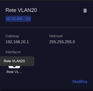
Setting up VLAN

I’m using a Flint 2 (GL-MT6000) on the latest firmware (4.11.0). I want to create a new VLAN, bind it to its own SSID, and route that SSID’s traffic through a VPN tunnel, separate from my main and guest networks.

There are several VLAN topics on the forum and in the documentation, but I couldn’t find an official guide that shows how to create a new VLAN, tie it to its own SSID, and route that traffic through a VPN on the Flint 2.

I was hoping to find a single guide that ties all of this together, So far I’ve created the VLAN and set up its netmask and subnet, and I assume the next step would be to get into LuCI.

Hi,

You can follow the steps below to configure Wi-Fi for your custom VLAN.

  1. In our example, the network interface is named vlan20.
  2. Log in to the router via SSH and run the following commands
    This example on a Flint 2 running firmware 4.11.0 and creates Wi-Fi on both 2.4 GHz and 5 GHz.
# Customize these settings
NET='vlan20'
SSID='VLAN20'
WIFI_PASSWORD='ChangeThisPassword123'

# Keep the VLAN bridge available without wired ports
BRIDGE="$(uci -q get "network.${NET}.device")"
for SECTION in $(uci show network | sed -n 's/^network\.\(.*\)=device$/\1/p'); do
    if [ "$(uci -q get "network.${SECTION}.name")" = "$BRIDGE" ] &&
       [ "$(uci -q get "network.${SECTION}.type")" = 'bridge' ]; then
        uci set "network.${SECTION}.bridge_empty=1"
    fi
done

# Create the 2.4 GHz Wi-Fi
uci set wireless.vlan20_2g='wifi-iface'
uci set wireless.vlan20_2g.device='mt798611'
uci set wireless.vlan20_2g.mode='ap'
uci set wireless.vlan20_2g.network="$NET"
uci set wireless.vlan20_2g.ifname='ra4'
uci set wireless.vlan20_2g.ssid="$SSID"
uci set wireless.vlan20_2g.encryption='psk2'
uci set wireless.vlan20_2g.key="$WIFI_PASSWORD"
uci set wireless.vlan20_2g.disabled='0'

# Create the 5 GHz Wi-Fi
uci set wireless.vlan20_5g='wifi-iface'
uci set wireless.vlan20_5g.device='mt798612'
uci set wireless.vlan20_5g.mode='ap'
uci set wireless.vlan20_5g.network="$NET"
uci set wireless.vlan20_5g.ifname='rax4'
uci set wireless.vlan20_5g.ssid="$SSID"
uci set wireless.vlan20_5g.encryption='psk2'
uci set wireless.vlan20_5g.key="$WIFI_PASSWORD"
uci set wireless.vlan20_5g.disabled='0'

unset WIFI_PASSWORD

# Save and reboot
uci commit network
uci commit wireless
sync
reboot
  1. Replace the following settings with your own values.
    Network interface: Replace NET='vlan20' with the network interface associated with your VLAN.
    Wi-Fi SSID: Replace SSID='VLAN20' with your preferred Wi-Fi name.
    Wi-Fi password: Replace WIFI_PASSWORD='ChangeThisPassword123' with your preferred password using 8–63 characters.
    image

After saving the settings and rebooting, the new Wi-Fi will be associated with your custom VLAN.

thank you! I will give it a try and update with result

Hi

Thank you for sharing this! I was facing a very frustrating issue where my wireless interface kept reverting to Client mode instead of functioning in Master (AP) mode bound to the bridge.

Without setting bridge_empty=1 and explicitly matching the MediaTek devices (mt798611/mt798612) and interface names (ra4/rax4) via CLI as shown in your script, GL.iNet's internal background processes would constantly overwrite the wireless config and break the AP setup.

Could you please clarify the exact step-by-step sequence to follow from the very beginning (starting from scratch via SSH, without touching LuCI at all) to properly define the VLAN interface, firewall zones, and then run this script?

I want to make sure I don't miss any prerequisite CLI commands before executing the wireless configuration commands above. Thanks!

Hi, you can use either of the following methods to create the network, then follow the wireless configuration in our earlier reply.

The examples below use a Flint 2 running firmware 4.11, with VLAN ID 20, network interface vlan20, and subnet 192.168.20.0/24.

Option 1: Create the network entirely through SSH

For a new setup, the commands below create the bridge, network interface, DHCP server, and firewall rules for Wi-Fi clients.

Please use an unused VLAN ID and subnet, and run this example when the vlan20 network has not yet been created.

# Back up the existing configuration
umask 077
BACKUP="/root/vlan-backup-$(date +%Y%m%d-%H%M%S)"
mkdir "$BACKUP"
cp -p /etc/config/network /etc/config/dhcp \
  /etc/config/firewall /etc/config/wireless "$BACKUP/"

# Create the network, DHCP server, and firewall rules
uci batch <<'EOF'
set network.bridge_vlan20='device'
set network.bridge_vlan20.name='br-vlan20'
set network.bridge_vlan20.type='bridge'
set network.bridge_vlan20.bridge_empty='1'

set network.vlan20='interface'
set network.vlan20.device='br-vlan20'
set network.vlan20.proto='static'
set network.vlan20.ipaddr='192.168.20.1'
set network.vlan20.netmask='255.255.255.0'
set network.vlan20.display_name='vlan20'
set network.vlan20.vlan_id='20'

set dhcp.vlan20='dhcp'
set dhcp.vlan20.interface='vlan20'
set dhcp.vlan20.start='100'
set dhcp.vlan20.limit='150'
set dhcp.vlan20.leasetime='12h'
set dhcp.vlan20.ignore='0'

set firewall.vlan20='zone'
set firewall.vlan20.name='vlan20'
add_list firewall.vlan20.network='vlan20'
set firewall.vlan20.input='REJECT'
set firewall.vlan20.output='ACCEPT'
set firewall.vlan20.forward='REJECT'

set firewall.vlan20_wan='forwarding'
set firewall.vlan20_wan.src='vlan20'
set firewall.vlan20_wan.dest='wan'

set firewall.vlan20_dhcp='rule'
set firewall.vlan20_dhcp.name='Allow-DHCP-vlan20'
set firewall.vlan20_dhcp.src='vlan20'
set firewall.vlan20_dhcp.proto='udp'
set firewall.vlan20_dhcp.dest_port='67'
set firewall.vlan20_dhcp.family='ipv4'
set firewall.vlan20_dhcp.target='ACCEPT'

set firewall.vlan20_dns='rule'
set firewall.vlan20_dns.name='Allow-DNS-vlan20'
set firewall.vlan20_dns.src='vlan20'
set firewall.vlan20_dns.proto='tcp udp'
set firewall.vlan20_dns.dest_port='53'
set firewall.vlan20_dns.target='ACCEPT'

commit network
commit dhcp
commit firewall
EOF

These rules allow DHCP, DNS, and forwarding to WAN while keeping forwarding to other local firewall zones blocked by default.


Option 2: Create the VLAN through the firmware 4.11 Web interface

Go to NETWORK → LAN, click Add, and enter the following settings.

  • Name :vlan20
  • VLAN ID:20
  • Gateway :192.168.20.1
  • Netmask :255.255.255.0
    The Admin Panel creates the initial network, DHCP, and firewall configuration for this workflow.
    You can refer to the VLAN Networks guide for the Web configuration steps.
    LAN - GL.iNet Router Docs 4

Once the network is created, use the same wireless configuration from our earlier reply, then reboot the router.

Tomorrow i'll try, thank you very much for help.

The script to create the VLAN worked without any issues. Fast forward, after setting up the vpn tunnel and the global policy both are up and running.

Initally, the device(AndroidTV) had a working connection, however the traffic was bypassing the tunnel. I had unplugged and reconnected in between, afterward it wasn't getting internet. At first, I thought the DHCP wasn't able to hand out dns server, but if was true, it wouldn't show an IP and a gateway

I'm kind of wondering what might have happened, few things comes to mind

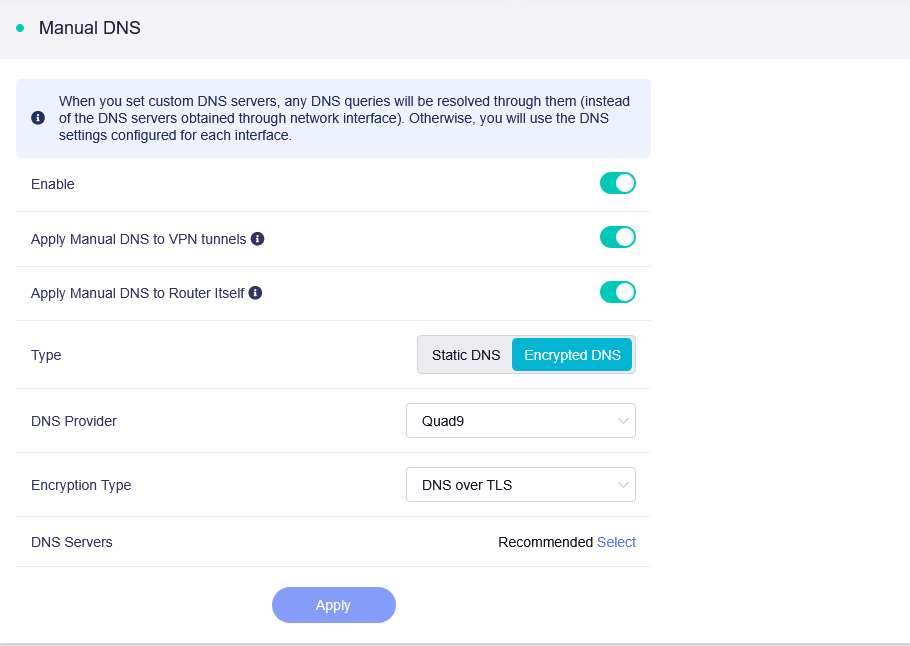
  • DNS issue, whether it can't reach the upstream queries after switching from “use VPN tunnel” to manual DNS (Quad9)?
    can’t reach, or the upstream queries are going out the WAN and being dropped once traffic is forced into the tunnel.

Current setup:
DNS mode: Using manual DNS, though VPN was initally enabled after config
VPN tu

nnel: Up and running
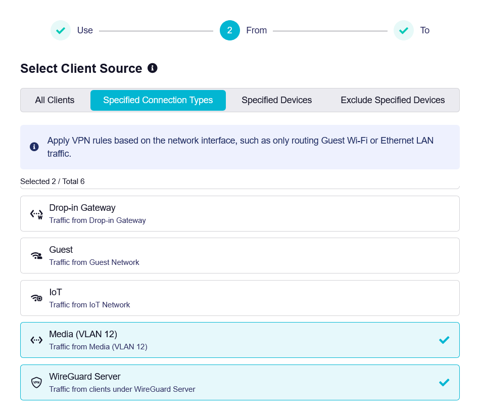
VPN Policy: From the device, To route all traffic

Security Settings:

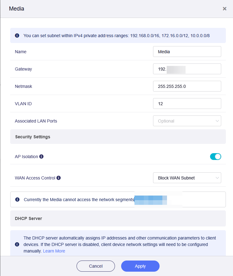
  • VLAN AP Isolation: enabled
  • WLAN Access Control: Block WAN Subnet


I spent yesterday troubleshooting and isolating the issue. When I stopped the VPN, the Android TV instantly got internet back. I then revisited the VPN policy’s client source list and found that the VLAN and additionally WireGuard entry, which hadn’t shown up prior. After starting the VPN server under VPN Client Profile, I confirmed the TV’s traffic was working and going through the configured tunnel

.

VLAN20 has been created successfully; however,
I am unable to connect to it.
Under "Network > Wireless," I see that the status is "disabled"
and "wireless not associated." Why? It seems a copy of default 2.4g

Hi,

Could you please confirm whether you rebooted the router after running the wireless configuration commands?

Please log in via SSH, run the following commands, and share the output so we can check the wireless interfaces and their bridge assignments.

# Firmware version
cat /etc/glversion

# Wireless configuration, excluding passwords
uci show wireless | grep -E '=wifi-device|=wifi-iface|\.device=|\.mode=|\.ifname=|\.network=|\.ssid=|\.disabled='

# Network interfaces and bridges
uci show network | grep -E '=interface|=device|\.name=|\.type=|\.device=|\.ports=|\.ipaddr=|\.netmask=|\.vlan_id=|\.bridge_empty=|\.disabled='

# Active interfaces and bridge membership
ip link show
brctl show

# Wireless runtime status
iwinfo

Please also let us know the SSID you configured and whether it appears in your phone’s available Wi-Fi networks.

Thank you for your understanding and cooperation.

@charles2 Would this same command work for the Flint 3 model GL-BE9300?

Hi,

For the GL-BE9300 (Flint 3), please use the following commands to create custom Wi-Fi networks on the 2.4 GHz, 5 GHz, and 6 GHz bands.

This example uses the existing vlan20 network interface and connects all three Wi-Fi networks to it.

(
set -e

# Customize these settings
NET='vlan20'
SSID='VLAN20'
WIFI_PASSWORD='ChangeThisPassword123'

IF_2G='wlan05'
IF_5G='wlan15'
IF_6G='wlan24'

# Check the existing network and radios
[ "$(uci -q get "network.$NET")" = 'interface' ] || {
    echo "Network interface not found: $NET"
    exit 1
}

for RADIO in wifi0 wifi1 wifi2; do
    [ "$(uci -q get "wireless.$RADIO")" = 'wifi-device' ] || {
        echo "Wireless device not found: $RADIO"
        exit 1
    }
done

# Avoid overwriting existing Wi-Fi configurations
for SECTION in vlan20_2g vlan20_5g vlan20_6g; do
    if uci -q get "wireless.$SECTION" >/dev/null; then
        echo "Wi-Fi section already exists: $SECTION"
        exit 1
    fi
done

for IFNAME in "$IF_2G" "$IF_5G" "$IF_6G"; do
    if uci show wireless | grep -Fq ".ifname='$IFNAME'" ||
       ip link show dev "$IFNAME" >/dev/null 2>&1; then
        echo "Wireless interface name already in use: $IFNAME"
        exit 1
    fi
done

# Keep the VLAN bridge available without wired ports
BRIDGE="$(uci -q get "network.$NET.device")"

for SECTION in $(uci show network |
    sed -n 's/^network\.\(.*\)=device$/\1/p'); do
    if [ "$(uci -q get "network.$SECTION.name")" = "$BRIDGE" ] &&
       [ "$(uci -q get "network.$SECTION.type")" = 'bridge' ]; then
        uci set "network.$SECTION.bridge_empty=1"
    fi
done

# Create the 2.4 GHz Wi-Fi
uci set wireless.vlan20_2g='wifi-iface'
uci set wireless.vlan20_2g.device='wifi0'
uci set wireless.vlan20_2g.mode='ap'
uci set wireless.vlan20_2g.network="$NET"
uci set wireless.vlan20_2g.ifname="$IF_2G"
uci set wireless.vlan20_2g.ssid="$SSID"
uci set wireless.vlan20_2g.encryption='psk2+ccmp'
uci set wireless.vlan20_2g.sae='0'
uci set wireless.vlan20_2g.key="$WIFI_PASSWORD"
uci set wireless.vlan20_2g.hidden='0'
uci set wireless.vlan20_2g.isolate='0'
uci set wireless.vlan20_2g.disabled='0'

# Create the 5 GHz Wi-Fi
uci set wireless.vlan20_5g='wifi-iface'
uci set wireless.vlan20_5g.device='wifi1'
uci set wireless.vlan20_5g.mode='ap'
uci set wireless.vlan20_5g.network="$NET"
uci set wireless.vlan20_5g.ifname="$IF_5G"
uci set wireless.vlan20_5g.ssid="$SSID"
uci set wireless.vlan20_5g.encryption='psk2+ccmp'
uci set wireless.vlan20_5g.sae='0'
uci set wireless.vlan20_5g.key="$WIFI_PASSWORD"
uci set wireless.vlan20_5g.hidden='0'
uci set wireless.vlan20_5g.isolate='0'
uci set wireless.vlan20_5g.disabled='0'

# Create the 6 GHz Wi-Fi with WPA3-SAE
uci set wireless.vlan20_6g='wifi-iface'
uci set wireless.vlan20_6g.device='wifi2'
uci set wireless.vlan20_6g.mode='ap'
uci set wireless.vlan20_6g.network="$NET"
uci set wireless.vlan20_6g.ifname="$IF_6G"
uci set wireless.vlan20_6g.ssid="$SSID"
uci set wireless.vlan20_6g.encryption='ccmp'
uci set wireless.vlan20_6g.sae='1'
uci set wireless.vlan20_6g.sae_pwe='1'
uci set wireless.vlan20_6g.key="$WIFI_PASSWORD"
uci set wireless.vlan20_6g.hidden='0'
uci set wireless.vlan20_6g.isolate='0'
uci set wireless.vlan20_6g.disabled='0'

# Save the configuration and reboot
uci commit network
uci commit wireless
reboot
)

Thanks, I ran the code but my the interface is showing up under the main network not the vlan created. How do I delete a network? There doesn't seems to be an option in the GUI.

Active interfaces and bridge membership

# ip link show
1: lo: <LOOPBACK,UP,LOWER_UP> mtu 65536 qdisc noqueue state UNKNOWN mode DEFAULT group default qlen 1000
link/loopback 00:00:00:00:00:00 brd 00:00:00:00:00:00
2: eth0: <BROADCAST,MULTICAST,UP,LOWER_UP> mtu 1500 qdisc fq_codel state UP mode DEFAULT group default qlen 1000
link/ether 32:af:b5:df:89:f9 brd ff:ff:ff:ff:ff:ff
3: eth1: <BROADCAST,MULTICAST,UP,LOWER_UP> mtu 1500 qdisc htb state UP mode DEFAULT group default qlen 1000
link/ether 94:83:c4:a2:94:ff brd ff:ff:ff:ff:ff:ff
4: lan2@eth0: <NO-CARRIER,BROADCAST,MULTICAST,UP> mtu 1500 qdisc noqueue master br-iot state LOWERLAYERDOWN mode DEFAULT group default qlen 1000
link/ether 94:83:c4:a2:95:01 brd ff:ff:ff:ff:ff:ff
5: lan3@eth0: <NO-CARRIER,BROADCAST,MULTICAST,UP> mtu 1500 qdisc noqueue master br-lan state LOWERLAYERDOWN mode DEFAULT group default qlen 1000
link/ether 94:83:c4:a2:95:01 brd ff:ff:ff:ff:ff:ff
6: lan4@eth0: <BROADCAST,MULTICAST,UP,LOWER_UP> mtu 1500 qdisc noqueue master br-lan state UP mode DEFAULT group default qlen 1000
link/ether 94:83:c4:a2:95:01 brd ff:ff:ff:ff:ff:ff
7: lan5@eth0: <BROADCAST,MULTICAST,UP,LOWER_UP> mtu 1500 qdisc noqueue master br-lan state UP mode DEFAULT group default qlen 1000
link/ether 94:83:c4:a2:95:01 brd ff:ff:ff:ff:ff:ff
8: lan1@eth0: <NO-CARRIER,BROADCAST,MULTICAST,UP> mtu 1500 qdisc noqueue master br-lan state LOWERLAYERDOWN mode DEFAULT group default qlen 1000
link/ether 94:83:c4:a2:95:01 brd ff:ff:ff:ff:ff:ff
9: ra0: <BROADCAST,MULTICAST,UP,LOWER_UP> mtu 1500 qdisc fq_codel master br-lan state UP mode DEFAULT group default qlen 1000
link/ether ea:75:96:8d:e9:43 brd ff:ff:ff:ff:ff:ff
10: br-guest: <BROADCAST,MULTICAST,UP,LOWER_UP> mtu 1500 qdisc htb state UP mode DEFAULT group default qlen 1000
link/ether a6:a5:45:16:65:c3 brd ff:ff:ff:ff:ff:ff
11: br-iot: <BROADCAST,MULTICAST,UP,LOWER_UP> mtu 1500 qdisc htb state UP mode DEFAULT group default qlen 1000
link/ether 56:fc:7a:d1:0d:8d brd ff:ff:ff:ff:ff:ff
12: br-lan: <BROADCAST,MULTICAST,UP,LOWER_UP> mtu 1500 qdisc htb state UP mode DEFAULT group default qlen 1000
link/ether 94:83:c4:a2:95:01 brd ff:ff:ff:ff:ff:ff
17: ra1: <BROADCAST,MULTICAST,UP,LOWER_UP> mtu 1500 qdisc fq_codel master br-guest state UNKNOWN mode DEFAULT group default qlen 1000
link/ether 76:04:20:9d:68:b2 brd ff:ff:ff:ff:ff:ff
18: ra2: <BROADCAST,MULTICAST,UP,LOWER_UP> mtu 1500 qdisc fq_codel master br-iot state UNKNOWN mode DEFAULT group default qlen 1000
link/ether ba:72:05:2d:4b:81 brd ff:ff:ff:ff:ff:ff
19: ra3: <BROADCAST,MULTICAST> mtu 1500 qdisc noop state DOWN mode DEFAULT group default qlen 1000
link/ether 00:00:00:00:00:00 brd ff:ff:ff:ff:ff:ff
20: rax0: <BROADCAST,MULTICAST> mtu 1500 qdisc fq_codel state DOWN mode DEFAULT group default qlen 1000
link/ether 94:83:c4:a2:95:02 brd ff:ff:ff:ff:ff:ff
21: rax1: <BROADCAST,MULTICAST> mtu 1500 qdisc fq_codel state DOWN mode DEFAULT group default qlen 1000
link/ether 96:83:c4:a2:95:02 brd ff:ff:ff:ff:ff:ff
22: rax2: <BROADCAST,MULTICAST> mtu 1500 qdisc noop state DOWN mode DEFAULT group default qlen 1000
link/ether 98:83:c4:a2:95:02 brd ff:ff:ff:ff:ff:ff
23: rax3: <BROADCAST,MULTICAST> mtu 1500 qdisc noop state DOWN mode DEFAULT group default qlen 1000
link/ether 00:00:00:00:00:00 brd ff:ff:ff:ff:ff:ff
24: rax4: <BROADCAST,MULTICAST,UP,LOWER_UP> mtu 1500 qdisc fq_codel state UNKNOWN mode DEFAULT group default qlen 1000
link/ether 16:77:c9:be:4f:92 brd ff:ff:ff:ff:ff:ff
25: apcli0: <NO-CARRIER,BROADCAST,MULTICAST,UP> mtu 1500 qdisc fq_codel state DOWN mode DEFAULT group default qlen 1000
link/ether 92:83:c4:a2:95:02 brd ff:ff:ff:ff:ff:ff
26: apclix0: <NO-CARRIER,BROADCAST,MULTICAST,UP> mtu 1500 qdisc fq_codel state DOWN mode DEFAULT group default qlen 1000
link/ether 9e:83:c4:a2:95:02 brd ff:ff:ff:ff:ff:ff
27: wgserver: <POINTOPOINT,NOARP,UP,LOWER_UP> mtu 1420 qdisc noqueue state UNKNOWN mode DEFAULT group default qlen 1000
link/none
28: wgclient1: <POINTOPOINT,NOARP,UP,LOWER_UP> mtu 1420 qdisc noqueue state UNKNOWN mode DEFAULT group default qlen 1000
link/none
31: br-lan-ifb: <BROADCAST,NOARP,UP,LOWER_UP> mtu 1500 qdisc htb state UNKNOWN mode DEFAULT group default qlen 1000
link/ether f6:2c:9b:8d:45:ee brd ff:ff:ff:ff:ff:ff
32: br-guest-ifb: <BROADCAST,NOARP,UP,LOWER_UP> mtu 1500 qdisc htb state UNKNOWN mode DEFAULT group default qlen 1000
link/ether 1e:52:f9:7e:9f:90 brd ff:ff:ff:ff:ff:ff
33: br-iot-ifb: <BROADCAST,NOARP,UP,LOWER_UP> mtu 1500 qdisc htb state UNKNOWN mode DEFAULT group default qlen 1000
link/ether ca:8b:0d:1c:37:03 brd ff:ff:ff:ff:ff:ff
34: eth1-ifb: <BROADCAST,NOARP,UP,LOWER_UP> mtu 1500 qdisc htb state UNKNOWN mode DEFAULT group default qlen 1000
link/ether ee:56:39:69:cc:19 brd ff:ff:ff:ff:ff:ff
35: br-vlan20-ifb: <BROADCAST,NOARP,UP,LOWER_UP> mtu 1500 qdisc htb state UNKNOWN mode DEFAULT group default qlen 1000
link/ether 72:2b:f4:6b:ee:43 brd ff:ff:ff:ff:ff:ff
root@PolNET:~# brctl show
bridge name bridge id STP enabled interfaces
br-iot 7fff.56fc7ad10d8d no lan2
ra2
br-lan 7fff.9483c4a29501 no lan4
lan5
ra0
lan3
lan1
br-guest 7fff.a6a5451665c3 no ra1

I can confirm that the device reboots after the SSH command and 
that the SSID is visible; however, every attempt to connect results in an error.
Hi,

To remove the three custom Wi-Fi networks created by the previous script, please run the following commands via SSH.
These commands keep your VLAN network configuration.

uci -q delete wireless.vlan20_2g
uci -q delete wireless.vlan20_5g
uci -q delete wireless.vlan20_6g
uci commit wireless
reboot

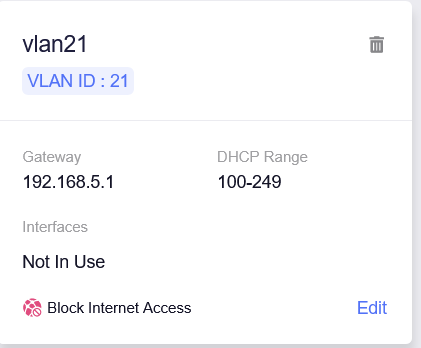
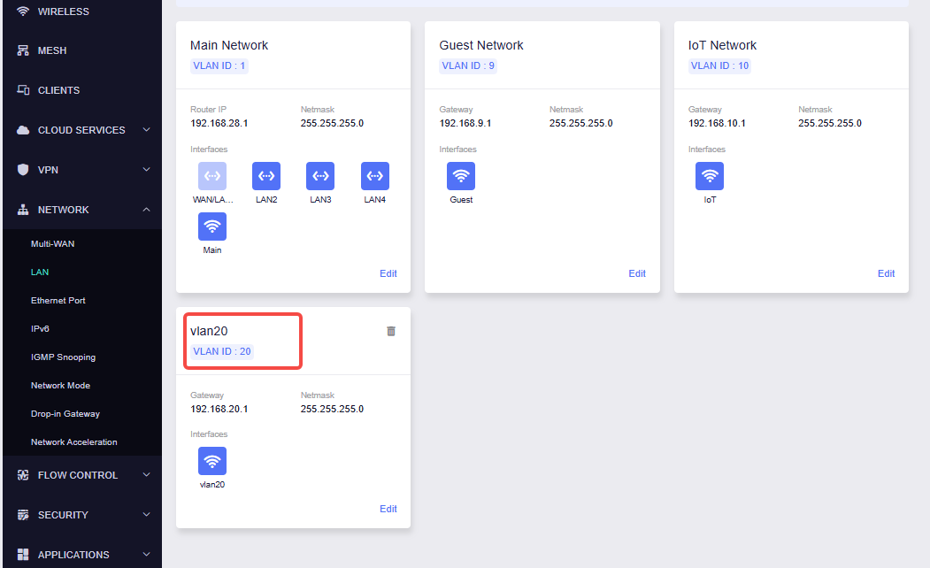
Your screenshot shows a network named vlan21, with VLAN ID 21 and gateway 192.168.5.1.
After removing the previously created Wi-Fi networks, change NET='vlan20' at the beginning of the previous script to the following, then run the complete script again.

NET='vlan21'

You can also change SSID='VLAN20' to SSID='VLAN21' if you would like the Wi-Fi name to match.
This will connect all three custom Wi-Fi networks to your existing VLAN 21.

Hi,

Thank you for sharing the command output.

The output shows that rax4 is active, but it has not joined the corresponding VLAN bridge, and br-vlan20 is missing from the bridge list.
Have you already created the vlan20 network, or would you like to connect this Wi-Fi to a different VLAN?
Could you please share a screenshot of the target VLAN’s network card under NETWORK → LAN, showing its name, VLAN ID, gateway, and interfaces?

This will help us confirm which network the custom Wi-Fi should be connected to.

Hi,

Is this screenshot from your current configuration, and are you still getting an error when connecting to this Wi-Fi?

If the issue persists, please run the following commands and share the output so we can check the VLAN configuration and its current bridge status.

uci -q show network.vlan20
uci show network | grep -E '=device|\.name=|\.type=|\.bridge_empty=|\.disabled='
ip link show
brctl show

This is current configuration, i can't connect to VLAN20 ssid, error connection every time i try.

Hi,

We tested these commands on our MT6000 and successfully created the Wi-Fi network, connected it to VLAN 20, and connected a client device to it.

Could you please share your router with our support team through GoodCloud so we can check the configuration and investigate the connection issue?

After sharing, please send us the device’s MAC address and router admin password via a forum private message.

Thank you for your cooperation.

How to send private messages: