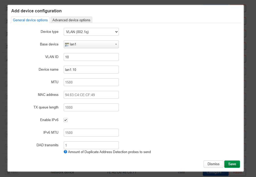
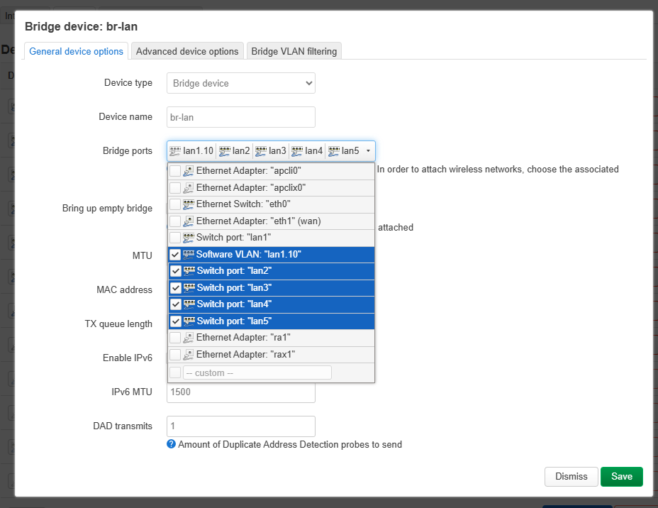
I have a GL-MT6000, firmware 4.8.3. I’ve tried, and failed, to configure VLAN’s a couple of times and just gave up. Instead, I’m using the existing networks to accomplish what I need.
LAN - both private wifi, ports 1, 2, & 3 on the router
GUEST - 5ghz guest wifi
IOT - 2.4ghz guest wifi, ports 4 & 5
Not as nice as having separate vlans for each, but it works.
I also have a a netgear GS308EP poe switch. It can create vlans as well. The problem is I have devices in both LAN and IOT networks that need poe. I know that I could use ports 1,2 for one and 3-8 for the other, but that wastes a port.
My limited understanding of the whole thing is if I knew what the vlan tags were, i could configure port 1 to have both as the trunk, port 2 for the LAN, and the rest for IOT. Trouble is, I can’t figure out what those names are. I suspect I only get those names if I have actual VLANs instead of using the existing ones the way I am.
I can’t recall exactly what the problem was with the vlans. it all seems so straightforward. I’d almost get to the end and lose access to one or the other. My guess is firewall, but I have a very loose grasp on the whole concept, so it was impossible for me to even begin to troubleshoot.
Thanks for staying with me until the end. My question is, can I do this with the router configured as described or would I need to create actual VLAN’s? If I need actual vlan’s, i’ll just have to lose that extra port. Thanks!